Overview
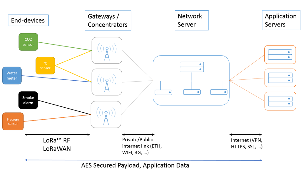
A LoRaWAN network is organized in a star-of-stars topology in which gateways relay messages between end devices and a central network server at the backend.
The frequencies used by LoRaWAN depend on the geographic region and its radio spectrum regulations: 868 MHz (EU), 915 MHz (US) and 920 MHz (Asia).
The end-device performs random frequency hopping and can use any of the possible data rates.
The datarate of the connection can be changed by modifying the spreading factor in order to adapt to the range.
The communication between the devices and the network is bi-directional, both uplink and downlink messages are possible.
All communications are secured: the messages are encrypted using AES with a key length of 128 bits.
Three distinct classes of end-devices exist in the LoRaWAN protocol. For the moment, only 2 classes are used for Watteco’s sensors:
- Class A (sleeping devices)
Downlink frames can only be transmitted after an uplink transmission by the sensor. Once the sensor sends an uplink frame, the end-device will open two receiving windows: RX1 and RX2, the network can then send on one of these windows a frame that will be taken into account by the sensor.
When a sleeping device is not transmitting a frame it goes into a sleep mode where it does not listen to the network. This mode permits to reduce a lot the consumption of the sensor.
- Class C (awake devices)
The network can send at any time a frame; it will be received by the sensor. The device open receive windows continuously.
QR Code
Most of our products incorporate a QRCode based on the format defined by the LoRa Alliance [https://lora-alliance.org/resource_hub/tr005-lorawan-device-identification-qr-codes/]. This generic QRCode could facilitate the management of deployment of devices.
The QRCode use all mandatory fields and few optionals:
- SchemaID: D0
- JoinEUI : 70B3D5E75F600000
- DevEUI : unique
- ProfileID :
- VendorID : 0128
- VendorProfileID : internal ID which defines a specific decoding
- Proprietary [optional] : Family Code on 10 characters
- SerNum [optional] : Serial Number on 10 characters
- CheckSum [optional] : calculation based on CRC-16-MODBUS (https://www.lammertbies.nl/comm/info/crc-calculation)
Example:

LW:D0:70B3D5E75F600000:70B3D5E75E00BA1B:01280002:P5070197000:S002D8C4F14:C3532
with
- JoinEUI: 70B3D5E75F600000
- DevEUI: 70B3D5E75E00BA1B
- VendorID: 0128
- VendorProfileID: 0002
- Family Code : 50-70-197-000
- Serial Number: 002D8C4F14
- CRC: 3532
End Device Activation
In order to have a correct communication between the sensor and the network server, the server needs to know that the sensor exists, and to know its identifier on the network, and how to communicate with it. In other words, any Watteco’s sensor working on a public or private network has to be commissioned on this network. Nevertheless, there is two different ways to associate the end-device to the network:
- OTAA
For over-the-air activation, end-devices must follow a join procedure before participating in data exchanges with the network server.
The join procedure requires the end-device to be personalized with the following information before it starts the join procedure: a globally unique end-device identifier (DevEUI), the application identifier (AppEUI), and an AES-128 key (AppKey).
- ABP
Activation by personalization directly connects an end-device to a specific network.
Activating an end-device by personalization means that the DevEUI, the DevAddr and the two session keys NwkSKey and AppSKey are directly stored into the end-device and shared with the LoRaWAN server.
The network address of the sensor on the LoRaWAN network (DevAddr) consists of 32 bit, it identifies the end-device within the current network. The DevAddr is set on the 25 last bits of the DevEUI, and can be configured by a specific ZCL command. The nwkID is set to 0 by default.
Its format is as follows:
![]()
Example
DevEUI = 70B3D5E75E000001 → DevAddr = 00000001
DevEUI = 70B3D5E75F000002 → DevAddr = 01000002
All the information above is provided at the delivery of the products.
Watteco devices work in both OTAA and ABP. When the device is switched on, its first attempt is to be connected in OTAA. If it fails, the device sends a frame with ABP configuration.
This process of association is repeated after 1 minute while the device is trying to connect to the network by following a trickle timer which is multiplied by 2 after each try until a periodicity of 24h.
A specific reassociation feature (Only available on "Confirmed" Uplink Mode) is implemented by default in Watteco devices after each 4 days and after 100 frames if the sensor doesn't communicate with the network. It can be configured by a specific ZCL command (LoRaWAN Cluster).
Once the device is associated to the network, it preserves its applicative configuration and its mode of association even after a reboot. At the next reboot, the device works only in OTAA or ABP mode, dependly of the previous association. In ABP mode all network paramaters are preserved after rebooting. In OTAA mode, an association is done after each reboot.
End Device Communication
It is necessary to contact the operator to understand how to send downlink frames. The procedure can differ from an operator to another.
The communication between the end-device and the network is done through Fport 125.
Since April 2018, it is important to note that the sensor doesn't ask for acknowledgement by default. It is in "Unconfirmed" mode. It is possible to change this behaviour by sending a specific ZCL command (LoRaWAN Cluster). It is possible to verify the default setting directly in the .txt file including keys.
In order to give the possibility to the network to send data, the sleeping devices use a Trickle Timer system that permits to send regularly a Uplink frame to the network if no reports or batches have been configured. The Trickle Timer directly impacts the behavior of sleeping sensors.
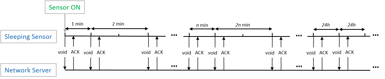
- When a sleeping sensor is switched on, it sends almost immediately a void frame (a LoRaWAN frame without payload) to the network server. When the sensor is commissioned on the server, it answers the sensor and acknowledges the void frame of the sensor.
- At the beginning, the trickle timer is at 1 min. The trickle timer is multiplied by two after each sending until it reaches 24 hours. It is the maximum value of the trickle timer. When this limit it reached, a void frame will be sent every 24 hours.
- A void frame will be sent by the end-device following this pattern if there is no report configured. If reports are configured on the device, the void frames will be sent until the trickle timer becomes bigger than the maximum reporting interval.
- After association, some devices have a connectivity feature. These send 10 void frames spaced 30 seconds apart.
On all devices which are activated by a reed switch, there is a specific function which avoiding to send a lot of join procedure after a power cycle (caused by a power failure or battery end of life). A 20 minutes timer is started after switching on the device, during this timing if there is a power cycle then the next join procedure will be done after 20 minutes. It is possible to desactivate this feature by sending on fport 125 : 1105800400070800 (To reactivate it: 1105800400070801).
Applicative layer
The application layer protocol implemented in Watteco’s sensors leverages on ZCL binary format. This combination of ZCL on top of a low power LoRa network should not be confused with “ZigBee®” technology, which uses its own network layer, not based on LoRa and operating at 2.4GHz. Watteco sensors range can be up to 20 times the range of typical ZigBee® sensors.
Cluster
A cluster is a related collection of attributes and commands, which together define a communications interface towards the distant device. It is an application message, which may be a container for one or more attributes.
Different clusters has been implemented in order to manage Watteco sensors.
Attribute
This is a data entity which represents a physical quantity or state. This data is communicated using commands.
In order to communicate with clusters and atttributes, it is possible to send generic commands.
End Point
The application protocol implements the notion of “Endpoint number” to enable multiple instances of each cluster type on a given device. Different clusterIDs may share a common endpoint number but two instances of a given clusterID must have different endpoint numbers.
The “Endpoint number” bits are distributed in the first byte of LoRaWAN payload as described below. Therefore an endpoint number can take 32 different values.
Fctrl (Frame Control) bitfield is encoded as follows:
| Endpoint number (0-31) | Reserved (Must keep these value) | Endpoint number (0-31) | !Batch report | ||||
|---|---|---|---|---|---|---|---|
| bit 7 | bit 6 | bit 5 | bit 4 | bit 3 | bit 2 | bit 1 | bit 0 |
| EndPoint_bit 2 | EndPoint_bit 1 | EndPoint_bit 0 (LSB) | 1 | 0 | EndPoint_bit 4 (MSB) | EndPoint_bit 3 | 0: Batch 1: others |
The following table gives the corresponding Fctrl to each Endpoint number:
| Fctrl | Endpoint |
|---|---|
| 0x11 | 0 |
| 0x31 | 1 |
| 0x51 | 2 |
| 0x71 | 3 |
| 0x91 | 4 |
| 0xB1 | 5 |
| 0xD1 | 6 |
| 0xF1 | 7 |
| 0x13 | 8 |
| 0x33 | 9 |
Two types of reports exist in the applicative feature of Watteco sensors:
Standard report
It sends a report on a periodicity or on a variation of the measure.
Three fields are important to configure a standard report:
Minimum reporting interval: minimum elapsed time since last “sending”, to accept “sending” a new sample.
Maximum reporting interval: maximum time without “sending” a new sample. When this time is elapsed, a new sample is automatically “sent”.
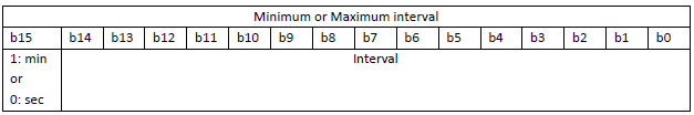
The minimum and maximum interval fields are on two bytes and define an interval in minutes or seconds depending on the first MSB bit as defined below:
Reportable change: minimum change on which a sample is sent.
To disable the configuration of a device, change the value of the minimum and maximum sending interval and the delta to 0.
A codec tool is available in python to decode the Standard report.
Batch report
It is used to concatenate, horodate and compress several samples of measure in the same reporting frame.
Discriminating usual zcl frames from batch report frames is done through the bit0 of Fctrl:
• 1: Usual ZCL frame (report or not)
• 0: Batch report frame.
The important fields to configure a batch report, are considered as below:
Field index: Each batch configuration is associated to a specific cluster/Endpoint/Attribut, however some clusters have multifield reportable attributes. The “Field index” parameter allows selecting the field to be reported in the attribute.
Most of the time this 1 byte “field index” is 0, like in clusters Temperature, Humidity, Binary, … But sometime it is necessary to define the requested field inside the attribute like in clusters Configuration, Simple metering or TIC.
Minimum recording interval: minimum elapsed time since last “recording”, to accept “recording” a new sample.
Maximum recording interval: maximum time without “recording” a new sample. When this time is elapsed, a new sample is automatically “recorded”.
The batch report is done on the minimum of the Maximum record interval of all batch’s configuration.
If “Batch” is set on more than one Cluster/Attribute/Endpoint then the effective “Maximum reporting interval” of the batch is configured to the minimum of them.
Recordable change: minimum change on which a dated sample is recorded. The Data type of this field is the same than the reportable value itself.
Resolution: it has the same format of the Recordable change and specify the resolution of the returned measure.
Tag value: it defines the “Label” representing the compressed measure in the “batch reporting” frame.
This field is one byte decomposed in two fields: 0bxxxxxzzz: zzz are the number of bits used for the Label size. The Label itself is contained in xxxxx, it is defined by a specific Endpoint/Cluster/Attribute/Field.
Even if a batch reporting could contain up to 6 different tags (different reported values), it will be pertinent to have only a few attributes values for a batch reporting. It is necessary to limit this according to the overall radio
performances, current protocol, sampling parameter requirement and physical profile measurement.
Tag requirements according to reports measures in a batch:
–All Tags have to be the same size
–All defined Labels have to be different than those that already exit.
–To make a new configuration, it is necessary to use the same label of the specific measure.
–It is important to dimension the size of the Tag related to the number of measures which will be batched. Longer the tag is, bigger the “batch reporting” will be.
| Label number | Tag label | Tag size |
|---|---|---|
| 1 or 2 | 0/1 | 1 |
| 3 or 4 | 00/01/11/10 | 2 |
| 5 or 6 or 7 or 8 | 000/001/010/011/100/101/110/111 | 3 |
| ... | ... | ... |
Procedure to define the tag value
•Define the number of measures to include in the batch report → Tag size
•Choose a label for each measure → Tag label
•Choose a resolution for each measure, the more it is small, the less measures will be compressed.
Uncompress batch tool
In association with the sensors, Watteco provides a software tool useful to uncompress the batch report payloads send by the Watteco’s sensors.
This software is provided as an executable and is called br_uncompress on a Linux OS or br_uncompress.exe on a Windows OS.
Usage
br_uncompress [-a] tagsize "taglabel, resolution, sampletype" "..."...
-a: The utility br_uncompress is called with the option -a, it says to the program to consider the buffer as ASCII hex bytes.
tagsize: the number of bits used for the label
The last triple argument list: each element of this list corresponds to an attribute which is batch reported. The parameters are:
–The label used to identify the attribute reported
–The resolution of the attribute
–The sample type of the attribute (it is specified in each cluster).
Interpretation of the uncompress tool results
After executing the command, the tool will give back a lot of text as answer. The results of the uncompression will be at the end of this answer after the label “UNCOMPRESS SERIE”:
UNCOMPRESS SERIE
cnt: number of counter
Timestamp
Timestamp Label Value
The first value is the frame counter of the batch frame sent by the sensor, it allows to identify a frame.
After the counter, all the other results can be seen as a column:
–The first column gives timestamps: the one in the first line corresponds to the sending time in seconds of the batch frame; after this one, all the others are the sampling time of the corresponding values.
In order to know the absolute sampling time for all the attribute values it is recommended to use the timestamp of the frame sending as a reference.The time of reception is known by the client, therefore from these two data and by doing a difference with the timestamp of each sample it is possible to find out the absolute sampling time for each value.
–The second column contains the label of each batch reported attribute.
–The third column contains the values of the batch reported attribute.
Download the br_uncompress tool
Generic commands
For each command, there is a generic format for the different features, it is listed as below:
- Read attribute request
| Fctrl | CmdID | ClusterID | AttributeID |
|---|---|---|---|
| 1 byte | 0x00 | 2 bytes | 2 bytes |
- Read attribute response
| Fctrl | CmdID | ClusterID | AttributeID | Status | Attribute type | Data |
|---|---|---|---|---|---|---|
| 1 byte | 0x01 | 2 bytes | 2 bytes | 1 byte | 1 byte | - |
- Configure reporting
Standard command
| Fctrl | CmdID | ClusterID | Reserved | AttributeID | Attribute type | Minimum reporting interval | Maximum reporting interval | Reportable change |
|---|---|---|---|---|---|---|---|---|
| 1 byte | 0x06 | 2 bytes | 0x00 | 2 bytes | 1 byte | 2 bytes | 2 bytes | - |
Batch command
| Fctrl | CmdID | ClusterID | Batch | AttributeID | Field index | Minimum recording interval | Maximum recording interval | Delta recordable change | Resolution | Tag |
|---|---|---|---|---|---|---|---|---|---|---|
| 1 byte | 0x06 | 2 bytes | 1 byte | 2 bytes | 1 byte | 2 bytes | 2 bytes | The size depends on the attribute type | The size depends on the attribute type | 1 byte |
- Configure reporting response
Standard command
| Fctrl | CmdID | ClusterID | Status | Reserved | AttributeID |
|---|---|---|---|---|---|
| 1 byte | 0x07 | 2 bytes | 1 byte | 0x00 | 2 bytes |
Batch command
| Fctrl | CmdID | ClusterID | Status | Reserved | AttributeID |
|---|---|---|---|---|---|
| 1 byte | 0x07 | 2 bytes | 1 bytes | 0x01 | 2 bytes |
- Read reporting configuration
Standard command
| Fctrl | CmdID | ClusterID | Reserved | AttributeID |
|---|---|---|---|---|
| 1 byte | 0x08 | 2 bytes | 0x00 | 2 bytes |
Batch command
| Fctrl | CmdID | ClusterID | Reserved | AttributeID |
|---|---|---|---|---|
| 1 byte | 0x08 | 2 bytes | 0x01 | 2 bytes |
- Read reporting configuration response
Standard command
| Fctrl | CmdID | ClusterID | Status | Reserved | AttributeID | Attribute type | Minimum reporting interval | Maximum reporting interval | Reportable change |
|---|---|---|---|---|---|---|---|---|---|
| 1 byte | 0x09 | 2 bytes | 1 byte | 0x00 | 2 bytes | 1 byte | 2 bytes | 2 bytes | - |
Batch command
| Fctrl | CmdID | ClusterID | Status | Batch | AttributeID | Field index | Minimum recording interval | Maximum recording interval | Delta recordable change | Resolution | Tag |
|---|---|---|---|---|---|---|---|---|---|---|---|
| 1 byte | 0x09 | 2 bytes | 1 byte | 1 byte | 2 bytes | 1 byte | 2 bytes | 2 bytes | The size depends on the attribute type | The size depends on the attribute type | 1 byte |
- Report attribute
Standard command
| Fctrl | CmdID | ClusterID | AttributeID | Attribute type | Reportable change |
|---|---|---|---|---|---|
| 1 byte | 0x0A | 2 bytes | 2 bytes | 1 byte | - |
Batch command
| Fctrl | |
|---|---|
| 0b.......0 | Use br_uncompress to decode the frame |
- Write attribute no response
| Fctrl | CmdID | ClusterID | AttributeID | Attribute type | Data |
|---|---|---|---|---|---|
| 1 byte | 0x05 | 2 bytes | 2 bytes | 1 byte | - |
Threshold, Alarms, Actions
Since release v3.x.2.yyyy, all devices integrate new features. It is possible to set Threshold, Alarms or Actions.
Several thresholds can be defined. Each threshold is subject to independent crossing monitoring management. This notion is used for both Report Standards and Report Batchs.
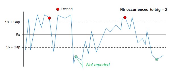
"Hysteresis" types can be activated:
- On association of a trigger interval notion of "Gap"
- On a number of sample occurrences exceeding the specified values
Simple Threshold / 2 occurences / increasing and decreasing
Simple Threshold / 2 occurences / increasing only
In the case of a request for one-way crossing signaling, the required crossing does not trigger a second alert (carry-over frame) unless the opposite crossing has been observed in the meantime.
Multi Threshold / 3 occurences / increasing and decreasing
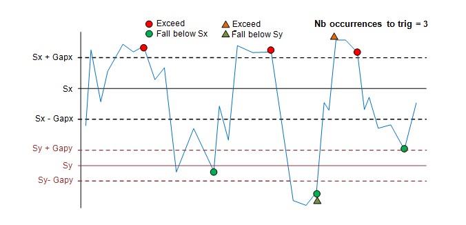
In the new configuration setting is possible to set on the report if it will be sent as an alarm, with the cause(increasing, decreasing of which threshold) of the report, if it will be confirmed or not...
It is possible to execute specific actions on crossing threshold, as change the periodicity of measure or the periodicity of sending. For that it is necessary to set one or several ZCL frame which will be executed.
The new configuration is defined below.
Reporting configuration request (0x06)
<EP>0x06<CID><RP><AID><Type><MinRpt><MaxRpt>[<Size>][<Port>][<CSD>[<FI>][<Val>][<Gap>][<Occ>[<OccH><OccL>]][<ActDesc>[<AoD><Val>]*]]*
with (<> is mandatory, [] is optional, * field could be repeated several times, [<Size>] is necessary for specific <Type> field 0x41-0x42 )
<RP>: Report parameters (U8)
| b0 | batch | 0: no |
| b1 | NoHeardePort | 0: no
1:yes (Report is sent on specific port defined as first byte of next parameters) |
| b2 | secured | 0: no
1: yes ( Force "confirmed" mode with repeat) This mode is priotary on the "Message type" of LoRaWAN Cluster. (Confirmed or not all frames) |
| b3 | secured if alarm | 0: no
1:yes ( Force confirmed with repeat, only if one of fired criteria is an alarm) |
| b5-b4 | cause request
(see Causes ) |
00: no
01: short (in the report a short cause of this report will be send) 10: long (in the report a long cause of this report will be send) 11: reserved |
| b7 | new mode configuration | 0: no (use the old format)
1:yes Note: Former batch conf should not exceed 63 bytes (0x0ssssss1 but never 0x1ssssss1) |
[<Port>]: Port (U8)
Field is present only if NoHeaderPort is set to 1. If a Port is defined, report is sent without header part (See TODO). Port Must be different than 0,6,125 and >223. The used port not be used by another attribute of any cluster.
<CSD>: Criteria Slot Descriptor (U8)
| b2-b0 | Criterion Index | 0 to 6, qualifying the 7 available criterion slots. number of slots is defined by each devices. |
| b4-b3 | Mode | 00: unused (to remove the specified slot. All other fields are not present)
01: delta (the following bytes defined delta value on which a report will be sent) 10: threshold (the following bytes defined threshold value on which a report will be sent) 11: threshold with actions (the following bytes defined threshold value on which a report will be sent and actions done ) |
| b5 | on fall | 0: no
1: yes |
| b6 | on exceed | 0: no
1: yes (mandatory in delta mode) |
| b7 | Alarm | 0: no
1: yes (The criterion is an alarm. the report will force Alarm ReportType 0x8A instead of 0x0A) |
[<FI>]: Field index (U8).
This field is optional. It is only present for multiple fields attributes (Power monitor, Simple-metering, Power quality,multiple-energy-power-metering,...). The values of the filed indexes are defined from 0 to n using their order of appearance in the attribute data read or reported. However the Configuration/NodePowerdescriptor attribute has got a specific field order definition.
<FI> is present only if <Type> is a non scalar value like (0x41: BYTES_STRING, 0x42: CHAR_STRING, 0x43: LONG_BYTES_STRING,0x4C: STRUCTURE_ORDEREDSEQUENCE)
[<Val>]: Value (depend on attribut or field type)
This field is present only if ‘Delta’, ‘Threshold’ or ‘Threshold with actions’ mode is set.
It is a part of the value on which the comparaison is done to validate the delta or threshold.
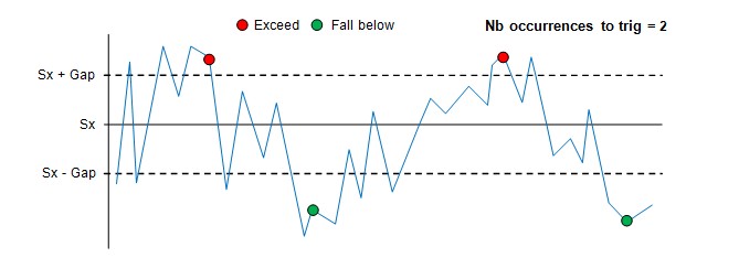
[<Gap>]: Gap (depend on attribut or field type)
This field is present only if ‘Threshold’ or ‘Threshold with actions’ mode is set.
It is the hysteresys value. It is a part of the value on which the comparaison is done to validate the delta or threshold.
the crossing is validated when new data is over or under Val + Gap or Val - Gap.
[<Occ>[<OccH><OccL>]]: Number of occurences of consecutive exceeds. (U8)<(U16)(U16)>
Report is triggered when the measure has crossed the specified limit and lasted during this number of occurences.
This field is present only with ‘Threshold’ mode. It must be greater than 0.
If b7 of Occ = 1 then 2 new field are present: OccH and OccL on 2 bytes each. OccH is the number of consecutive occurences to trig a report on Exceed, and OccLow the number of consecutive occurrence to trig on Fallen.
[<ActDesc>[<AoD><Val>]*]: These fields are present only with ‘Threshold with Actions’ mode.
The table of actions is available in configuration cluster and has to be configured for your own application.
It is possible to execute some actions on threshold, the linked report can be removed by configuration.
Notes:
- To remove all report on a specified attribut, the frame to send is :<EP>0x06<CID><0x80><AID><Type><MinRpt><MaxRpt>[<Size>]<0x00><0x01><0x02><0x03><0x04><0x05><0x06>
[<Size>] is necessary for specific <Type> field 0x41-0x42
- The <RP>, <MinRpt>, <MaxRpt> are updated at each new configuration. If configuration is sent in few frames, the last received configuration will be saved for these specific fields.
- All criteria for each slot are tested after a new measure. A report is sent if at least one crietria is activated.
- Old frame format configures the Criteria Index Slot 0 in delta mode.
- Criteria could be configured/deconfigured in several frames.
Reporting configuration response (0x07)
If the configuration integrates only delta mode and is not "secured", "alarm" or "report cause" then the frame is sent with <DIR>=0x00 or with <DIR>=0x80
<EP>0x07<CID><Status><DIR><AID>
U8 U8 U16 U8 U8 U16
<Status> = 0x00 when configuration is accepted
Read Reporting configuration Request (0x08)
The old format could be used, but it possible to receive an error (0x89) if the answer can't be formatted in the old format.
The request could be completed with the new fields <RP> and <CSD> to define the list of criteria slots. An error (0x89) is sent if the answer is too long.
<EP>0x08<CID><RP><AID>[<CSD>]*
U8 U8 U16 U8 U16 U8
Only the first bit has to be set, so <RP> = 0x80
Only the last 3 bits (b2-b0) are analysed on <CSD>.
Read Reporting configuration response (0x09)
If the configuration integrates only delta mode and is not "secured", "alarm" or "report cause" then the frame is sent on the old format.
In the other cases, the frame has the following format:
<EP>0x09<CID><Status><RP><AID><Type><MinRpt><MaxRpt>[Port][<CSD>[<FI>][<Val>][<Gap>][<Occ>[<OccH><OccL>]]]*
(see ReportingConfigurationRequest )
Report (0x0A et 0x8A)
By default the format is not changed: <EP>0x0A<CID> <AID><Type><Value>
With the feature the format could be different:
- If the criteria configured is an "alarm" then the report is sent due to cross an threshold then 0x0A is changed by 0x8A.
- If the configuration included a cause report then the frame is suffixed by short or long cause:
<EP>(0x0A|0x8A)<CID><AID><Type><Value>[Causes]
with
[Causes] Causes identify all criteria that have triggered the report. the format is :
<RP>[<CSD>[<FI>][<Val>[<Gap>][<Occ>[<OccH><OccL>]]]]*
with
| <RP> | Report parameters | |||||||||||||||
| <CSD> | Criterion Slot Descriptor for each fired criterion
This field is present only if “short cause” or “long cause” required and the corresponding criteria has been fired
|
|||||||||||||||
| [<FI>] | Field index. (see ReportingConfigurationRequest )
This field is present only if “long cause” required. |
|||||||||||||||
| [<Val>] | Value. (see ReportingConfigurationRequest )
This field is present only if “long cause” required. |
|||||||||||||||
| [<Gap>] | Gap. (see ReportingConfigurationRequest )
This field is present only with ‘Threshold’ mode and if “long cause” required. |
|||||||||||||||
| [<Occ>[<OccH><OccL>]] | (see ReportingConfigurationRequest )
This field is present only with ‘Threshold’ mode and if “long cause” required. |
