ModBus sensor
Declaration of conformity
Download the declaration of conformity.
Presentation
The ModBus sensor can either be a LoRaWAN class A sensor (50-70-080) or a LoRaWAN class C sensor (50-70-109).
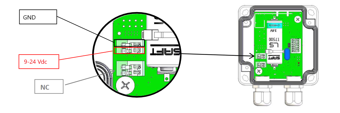
The class A sensor manages two different power supplies: one is external and may range from 9 to 24V, the other one is internal on a disposable 3.6V A-type battery. To use the external power supply, simply connect a compatible unit on the “Ext power” connector.
The ModBus sensor incorporates all the connections needed for an RS485 bus: A, B and GND. It also includes an internal antenna.
The ModBus sensor allows communication (via the LoRaWAN network) with any equipment that implements the ModBus protocol as slave. Thus, it works as a ModBus master.
The ModBus equipment to communicate with must use the RTU coding type and an RS485 bus as the physical link. Moreover, the ModBus equipment must support at least one of the baud rates in the following list: 1200, 2400, 4800, 9600, 19200, 38400, 57600 or 115200 bit/s.
If these prerequisites are fulfilled, the Watteco ModBus sensor is compatible with the equipment, and thus, can correctly communicate with it to get or set any modbus registers present inside the equipment. Thus the ModBus equipment is now LoRaWAN ready thanks to the sensor.
Family code / Release Note
The ModBus sensor family code is: 50-70-080-(003 and upper) [class A] or 50-70-109-(003 and upper) [class C]
For all other older release or see older revision documentation
Release note:
- 50-70-080-003 / 50-70-109-003: new casing, battery holder, Leds IHM
LoRaWAN release
v1.0.2 Region Parameter rev B
User guide
Installation and operation
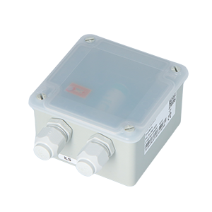
The housing is intended to be installed inside or outside a building but it must be protected from vertical water spray and direct sunlight.
The product is delivered disassembled. This enables the connection to the screw terminals.
Before connecting your cable strands to the product’s screw terminals, you must insert the cable gland’s nut and the seal.
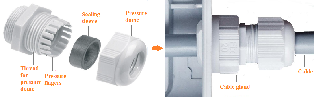
Then connect the wires to the different signal or power terminals that will be used.
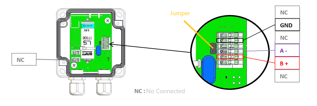
For the signal:
For the power:
For the connectors, we recommend using several 20-26 AWG single wires. As the connectors pinch the wires plugged inside approximately 4mm from the wire end, strip the wires over a length of approximately 5 to 6mm before plugging them into the connectors.
The cable to be used for RS485 communication must have some features to allow the signals to be correctly transferred from the ModBus sensor to the ModBus equipment, especially when there is a long distance to cover.
Watteco recommends the cable type (with cable lugs to crimp) shown in the following page: https://fr.rs-online.com/web/p/cables-industriels-multipaires-torsades/3827000/ (BELDEN 3105A.00152)
The RS485 bus signals must be connected to the corresponding signals on the ModBus equipment side. The Ground signal of the RS485 is generally connected to the shielding braid on both sides.
The RS485 output signal is ±3.3 Vdc, and the RS485 input accepts a signal ranging from -7 Vdc to +12 Vdc maximum.
Moreover, a terminating resistor for the RS485 bus is available on the ModBus sensor. By default, this resistor is enabled thanks to a 120Ohm jumper placed over the 2 contact pads. This resistor is not always needed to achieve good communication on the RS485 bus. The choice of enabling or disabling it is at the user's discretion. To enable it, leave the jumper on the pad. To disable it, remove the jumper.
Once the assembly is complete, the casing can be closed.
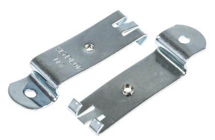
The housing is compatible with the following DIN rail adapter:
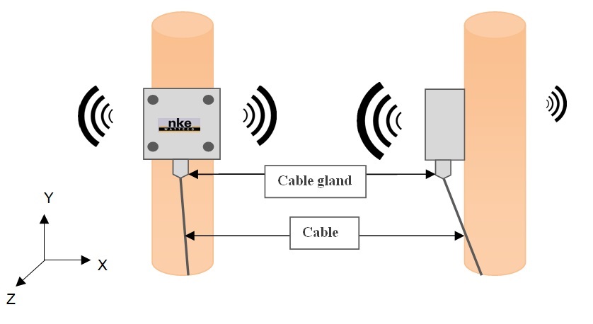
Radio propagation
In order for the sensor to operate correctly, the number of obstacles should be limited in order to avoid excessive radio wave attenuation. It is also important to place the sensor as high as possible. The cable gland should be positioned downward.
Autonomy
When powered by its 3.6V/3.6Ah internal disposable battery, the class A ModBus sensor autonomy is greater than 10 years for a report of 4 bytes (2 ModBus registers) with SF12 every 1 hour.
More examples of ModBus sensor autonomy on its disposable battery are shown below.
| Transmission periodicity | Number of ModBus registers reported | Battery life |
|---|---|---|
| 10 minutes | 2 or 3 | 2 years |
| 30 minutes | 2 or 3 | 7 years |
| 1 hour | 2 or 3 | > 10 years |
| 2 hours | 2 or 3 | > 15 years |
| 24 hours | 2 or 3 | > 15 years |
N.B.: The autonomy times here above are given for an end-device with SF12 in unconfirmed mode.
N.B. 2: As the class C device is only powered by an external power supply, its autonomy has no limitation.
Human Machine Interface
There are twoLEDs on the Modbus device:
ASSN: blinking until the association with a network is done.

CNF: blinking in configuration mode.
To start up the device, a magnet must be placed next to the sensor for one second (to the left of the cable gland). The red LED blinks quickly during this step. After one second, the red LED stops blinking and the green LED blinks slowly until the association is done.
To switch off the device, repeat the same operation by placing the magnet next to the sensor for 5 seconds. After those 5 seconds, the red LED blinks 5 times slowly.
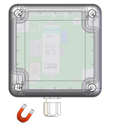
A reed switch is available under the sticker. A magnet can be used to activate it and perform specific actions on the sensor (switch off, switch on, reassociation…). When the reed switch is activated, the red LED blinks quickly.
- Configuration

| Way to trigger it | One passage of the magnet near the reed switch or specific ZCL command |
| Way to stop it | Another passage of the magnet or specific ZCL command |
| Effects on the sensor | The CONF led (red) blinks (3 sec. OFF, 3 sec. ON) and the sensor sends an uplink frame every minute. |
| Duration | The configuration mode lasts 10 minutes |
- A reassociation procedure can be requested if no downlink frame is received by the sensor during a given periodicity (4 days by default) or if a given number (100 by default) is reached or in case of failure (no acknowledgement received) by sending an applicative frame to the sensor or via the sensor’s IHM.
The sensor keeps the AppEUi and DevAddr configured, Confirmed/Unconfirmed configuration and all applicative configurations. However, LoRaWAN configurations (channel, data rate …) are lost.
| Way to trigger it | Three passages of the magnet near the reed switch or ZCL command from LoRaWAN cluster. |
| Effects on the sensor | The ASSN led (green) blinks as the “no commissioned sensor” LED is lit. |
- A factory reset is available on Watteco’s sensors. It deletes all the applicative settings saved in the flash memory (i.e. configured batches and reports will be deleted).
The sensor keeps the AppEUi and DevAddr configured. However, LoRaWAN configurations (channel, data rate…) and applicative configurations are lost.

| Way to trigger it | Two quick passages and a long passage of the magnet near the reed switch |
| Effects on the sensor | The CONF LED (red) and ASSN LED (green) blink at the same time briefly. All the applicative settings (for batches and reports) are deleted. The blinking is illustrated below this table. |
Applicative layer
Codecs are available to decode frames: Downloads
In the ModBus sensor, the Serial Master/Slave Protocol implements 8 EndPoints (software version v3.5.0.4294.4338) or 10 EndPoints (software version v3.5.0.4740). That means that up to 8 (or 10) requests can be managed by the ModBus sensor, thus up to 8 (or 10) reports with different configurations and different ModBus requests. The maximum modbus registers readable by request is 16.
| End Point | Cluster | Fctrl |
|---|---|---|
| 0 | Serial Master Slave Protocol | 0x11 |
| 1 | Serial Master Slave Protocol | 0x31 |
| 2 | Serial Master Slave Protocol | 0x51 |
| 3 | Serial Master Slave Protocol | 0x71 |
| 4 | Serial Master Slave Protocol | 0x91 |
| 5 | Serial Master Slave Protocol | 0xB1 |
| 6 | Serial Master Slave Protocol | 0xD1 |
| 7 | Serial Master Slave Protocol | 0xF1 |
| 8 (from v3.5.0.4740) | Serial Master Slave Protocol | 0x13 |
| 9 (from v3.5.0.4740) | Serial Master Slave Protocol | 0x33 |
This number of Endpoints allows a wide variety of exchanges between Watteco’s ModBus sensor and the ModBus equipment.
Furthermore, the ModBus sensors (class A or class C) integrate the following clusters.
| Cluster | Cluster name | Managed attributes |
|---|---|---|
| 0x0000 | Basic | All |
| 0x0050 | Configuration | All |
| 0x8004 | LoRaWAN | All |
| 0x8006 | Serial Interface | All |
| 0x8007 | Serial Master/Slave protocol | All |
| 0x8009 (from v3.5.0.4740) | Multi Master/Slave answers | All |
Default configuration
Since the ModBus sensor 50-70-080 and 50-70-109 is a very open sensor that is compatible with wide range of equipment, there is no default report configuration on the “Serial Master/Slave Protocol” cluster.
For the “Serial Interface” cluster, the default values for the attributes are as follows:
- Speed : 9600 bit/s
- Data bits : 8 bits
- Parity : None
- Stop bits : 1 bit
There is specific configuration for this device:
50-70-165: SHARKY 775 2018
50-70-181: SHARKY 775 2013
50-70-182: ITRON CF ECHO II / CF51 / CF55 / CF800
50-70-176: KAMSTRUP
Every change made to the default configuration must comply with the legal duty cycle (for example, the most restrictive in the EU is 0.1%, which corresponds to approximately 1 frame per hour with SF12)
ModBus exchange periodicity
The minimum ModBus exchange periodicity available is 1 minute. If in the configuration of the report, the minimum value is set under 1 minute, the sensor changes it to 1 minute. If the minimum value is more than 1 minute, the exchange periodicity depends on the minimum and maximum intervals in the report configuration.
If the minimum is set at 0 and the maximum at another value, then an exchange will be carried out every minute, and a report will be sent when the time reaches the maximum value (if delta is set to 0). If delta is set to 1, a first report will be sent after 1 minute. Afterwards, a report will be sent each time the answer from the ModBus equipment changes.
If the minimum is set at a value other than 0 and above 1 minute, then this value is the periodicity used by the sensor to send the request to the ModBus equipment.
Finally, if the maximum and minimum values are under 1 minute, the report will be sent every maximum period, but the ModBus answer sent on the LoRaWAN network will only be updated every minute.
Frame examples
All frames have to be sent on port 125
Configuration of serial link parameters
- Situation: the ModBus equipment to which the ModBus sensor is connected uses the following parameters on the serial link:
- Speed: 19200 bit/s
- Data bits: 7 bits
- Parity: Even
- Stop bits: 1 bit
- Solution: the solution is to configure all the serial link parameters using the “Serial Interface” cluster. There is just one EndPoint for this cluster on the ModBus sensor, thus the EndPoint is 0, we will use the “Write attribute no response” command (0x05) and the cluster ID is 0x8006. Thus, the different payloads to be sent to the ModBus sensor to correctly configure the serial link (on the FPort 125) can be found below. It can be seen that the payload to change the stop bit is here. However, it is not necessary since 1 bit is its actual default value.
Speed change on the serial interface → Applicative payload is: 11 05 8006 0000 22 004B00 0000 : Attribute ID (0x0000 -> Speed) 22 : Attribute Type (0x22 -> UINT24_TYPE) 004B00 : New value for the attribute (0x004B00 -> 19200 bits/s)
Data bits change on the serial interface → Applicative payload is: 11 05 8006 0001 20 07 0001 : Attribute ID (0x0001 -> DataBits) 20 : Attribute Type (0x20 -> UINT8_TYPE) 07 : New value for the attribute (0x07 -> 7 bits)
Parity change on the serial interface → Applicative payload is: 11 05 8006 0002 20 02 0002 : Attribute ID (0x0002 -> Parity) 20 : Attribute Type (0x20 -> UINT8_TYPE) 02 : New value for the attribute (0x02 -> Even parity)
Stop bit change on the serial interface → Applicative payload is: 11 05 8006 0003 20 01 0001 : Attribute ID (0x0003 -> StopBits) 20 : Attribute Type (0x20 -> UINT8_TYPE) 01 : New value for the attribute (0x01 -> 1 bit)
Configure a ModBus request
- Situation: we want to save a ModBus request on the second EndPoint of the ModBus sensor. This request should allow 2 registers of the ModBus equipment to be read from the address 0x140. The ModBus address of the equipment (thus, the ModBus slave address) is 0x23.
- Solution: the solution is to configure the request (Attribute ID: 0x0000) to use on the 2nd EndPoint (0x31) thanks to the command “Write Attribute No Response” (0x05), in the cluster “Serial Master/Slave Protocol” (0x8007)
Save a ModBus request on EndPoint 2 → Applicative payload is: 31 05 8007 0000 41 06 230301400002 0000 : Attribute ID (0x0000 -> Request) 41 : Attribute Type (0x41 -> BYTES_STRING) 06: Bytes string size (0x06 -> 6 bytes) 230301400002 : ModBus Request (without CRC): ModBus Slave Address: 0x23 ModBus Command: 0x03 (Read Holding Registers) ModBus register address: 0x0140 Number of registers to read: 0x0002
For more details about the different ModBus commands, please refer to the ModBus Application Protocol Specification, available on the official ModBus website: http://www.modbus.org/docs/Modbus_Application_Protocol_V1_1b.pdf
An interesting document in french on protocol Modbus: protocole-modbus.pdf
Configure a report on the ModBus answer
- Situation: now that the request on the second EndPoint has been correctly saved (see paragraph above), we want to report the answer of the ModBus slave to this request every 1 hour. In other words, we want to have the content of the 0x0140 and 0x0141 ModBus register every 1 hour.
- Solution: the solution is to configure a report with the command “Configure reporting” (0x06), on the second EndPoint (0x31) of the cluster “Serial Master/Slave Protocol” (0x8007), on the Attribute “Answer” (0x0001) with a periodicity of one hour.
Configure a report on the slave answer of EndPoint 2 → Applicative payload is: 31 06 8007 00 0001 41 803C 803C 01 00 0001 : Attribute ID (0x0001 -> Answer) 41 : Attribute Type (0x41 -> BYTES_STRING) 803C: Minimum reporting interval (0x803C -> 60 minutes or 1 hour) 803C: Maximum reporting interval (0x803C -> 60 minutes or 1 hour) 00 : Reportable change (0x00: a change in the ModBus answer does not trigger the sending of a report)
Configure a report on all the ModBus answers
- Situation: let's imagine that several ModBus requests have been saved on the ModBus sensor. And now the user wants to get all the ModBus answers from the requests, in one go and with the same periodicity. It allows the duty cycle of the sensor to be optimised. The user wants to have all these answers every 2 hours.
- Solution: the solution is to configure a report with the command “Configure reporting” (0x06), on the first EndPoint (0x11) of the cluster “Multi Master/Slave Answers” (0x8009), on the Attribute “Present Value” (0x0000) with a periodicity of two hours. The cluster used is described in details here.
Configure a report on all the slave ModBus answers → Applicative payload is: 11 06 8009 00 0000 41 8078 8078 01 00 0000 : Attribute ID (0x0000 -> Present value) 41 : Attribute Type (0x41 -> BYTES_STRING) 8078: Minimum reporting interval (0x8078 -> 120 minutes or 2 hours) 8078: Maximum reporting interval (0x8078 -> 120 minutes or 2 hours) 00 : Reportable change always disabled for this cluster
Known issues
- Modbus ClassC may stop periodic reports, on too fast consecutives DL "Direct exchanges":
- Version : All
- Issue: The periodic reportings of configured Answers may stop when :
- Two consecutive Modbus commands "Direct exchanges" are quickly send one after each other,
- AND the modbus commands return the 0x81 code (modbus command without response (timeout)).
- Workaround: Wait for the answer UL or at least 5seconds, before any new downlink modbus request from your application
