Smart plug
|
|
|
Declaration of conformity
Download the declaration of conformity
Presentation
The SmartPlug is a LoRaWAN class C device that uses the mains voltage as a power supply.
The SmartPlug includes an internal antenna.
The direct application for the SmartPlug is to control electrical devices thanks to their electric supplies, it can also measure the power consumption of the electric device plugged into it, and measure and evaluate the quality of the electrical mains to which it is plugged.
 |
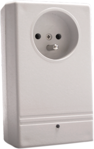
UK version and EU version (EU version < 50-70-003-004 only) |
|
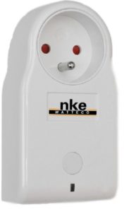
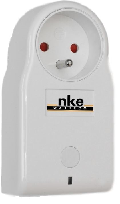
New EU version (50-70-003-005) !!! No button on this version !!! |
Family code
The family code of the SmartPlug devices is: 50-70-003-xxx
Installation and operation
Electrical characteristics
- Consumption: around 800mW
- Measure from 10W to 2300W. All measure below 10W is considered to 0W.
Installation
The housing is intended to be installed inside or outside a building but it must be protected from vertical water spray and direct sunlight.
Plug the SmarPlug into a wall socket, then plug an electrical device into it.
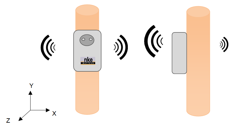
Radio propagation
In order for the sensor to operate correctly, the number of obstacles should be limited in order to avoid excessive radio wave attenuation. It is also important to place the sensor as high as possible.
Human Machine Interface
In order to switch the SmartPlug ON, plug it into a wall socket. The SmartPlug will automatically start.
One LED can be seen on the device. This LED can have 2 different colours:
- Green: blinking until the association with a network is done.

- Red: blinking when the user button is pressed
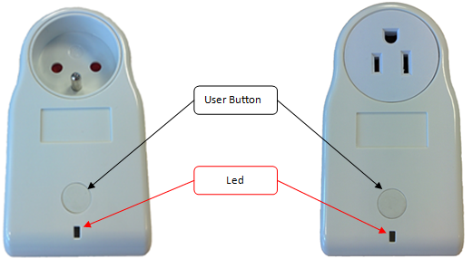
One press on the User Button will change the state of the SmartPlug (ON/OFF).
!!! The button is not available on the newest EU version (50-70-003-005) !!!
If the SmartPlug is rebooted, it will keep the last state it was on.
- A reassociation procedure can be requested if no downlink frame is received by the sensor during a given periodicity (4 days by default) or if a given number (100 by default) is reached or in case of failure (no acknowledgement received) by sending an applicative frame to the sensor or via the sensor’s IHM.
The sensor keeps the AppEUi and DevAddr configured, Confirmed/Unconfirmed configuration and all applicative configurations. However, LoRaWAN configurations (channel, data rate…) are lost.
| Way to trigger it | Three short presses on the USER button or ZCL command from LoRaWAN cluster. |
| Effects on the sensor | The ASSO LED (green) blinks as the “no commissioned sensor” LED is lit. |
- A factory reset is available on Watteco’s sensors. It deletes all the applicative settings saved in the flash memory (i.e. configured batches and reports will be deleted).
The sensor keeps the AppEUi and DevAddr configured. However, LoRaWAN configurations (channel, data rate…) and applicative configurations are lost.
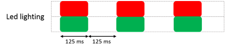
| Way to trigger it | Two short presses and one long press for approximately 7 seconds on the USER button. |
| Effects on the sensor | The CONF LED (red) and ASSO LED (green) blink at the same time briefly. All the applicative settings (for batches and reports) are deleted. The blinking is illustrated below this table. |
Applicative layer
Codecs are available to decode frames: Downloads
The SmartPlug device is an awake device. It implements the “On/Off” cluster associated with the output controlled by the relay, the “Power Quality” cluster and the “Simple-Metering-Like” cluster.
The SmartPlug integrates the following clusters:
| Cluster | Cluster name | Managed attributes |
|---|---|---|
| 0x0000 | Basic | All |
| 0x0050 | Configuration | All |
| 0x8004 | LoRaWAN | All |
| 0x0006 | ON/OFF | All |
| 0x0052 | Simple Metering Like | All |
| 0x8052 | Power Quality | All |
Default configuration
Currently delivered smartplug have a batch report configuration of Active energy instead of "former default standard report configuration". The parameters are:
- One batch report for active energy:
- Min 3 minutes (Sampling frequency),
- Max: 15 minutes (Batch Tx period),
- Batch parameters: Size: 1, Label 0, Variation 0 (no trig on delta), Resolution 1, Type 9 (I24)
So, the batch decoding parameters with batch online decoder should be: 1 0,1,9,ActiveEnergy
- One standard report on ON/OFF state change
Former default configuration:
If the smartplug does not send batches the default configuration should be the following one
- The device reports the simple metering (EndPoint 0 / Cluster Simple Metering /Attribute Current Metering) every hour.
Every change made to the default configuration must comply with the legal duty cycle (for example, the most restrictive in the EU is 0.1%, which corresponds to approximately 1 frame per hour with SF12)
Use cases
The direct application for the SmartPlug is to control electrical devices thanks to their electric supplies. The SmartPlug is plugged inside a wall socket. Then the device to be controlled has to be plugged into the SmartPlug’s socket. Once this quick installation is done, the electric device can be controlled through the LoRaWAN network to be either powered or not.
The SmartPlug also measures the power consumption of the electric device plugged into it. The table below summarizes all the values measured along with their unit.
| Measurement | Unit |
|---|---|
| Active Energy | W.h |
| Reactive Energy | VAR.h |
| Accumulation duration for energies | Number of minutes |
| Active Power | W |
| Reactive Power | VAR |
The SmartPlug measures and evaluates the quality of the electrical mains to which it is plugged. The table below represents the available indicators provided by the SmartPlug to evaluate the quality of the mains.
| Measurement | Description | Unit |
|---|---|---|
| Frequency | Current frequency seen by the SmartPlug | (x+22232)(Hz/1000) |
| Frequency min. | Minimum frequency seen by the SmartPlug | (x+22232)(Hz/1000) |
| Frequency max. | Maximum frequency seen by the SmartPlug | (x+22232)(Hz/1000) |
| VRMS | Current Root Mean Square Voltage of the main signal seen by the SmartPlug | (V/10) |
| VRMS min. | Minimum Root Mean Square Voltage of the main signal seen by the SmartPlug | (V/10) |
| VRMS max. | Maximum Root Mean Square Voltage of the main signal seen by the SmartPlug | (V/10) |
| OverVoltageNumber | Counter incremented by the SmartPlug each time a voltage peak exceeds the value set by the “Over voltage Threshold” in the Power Quality Cluster | Counter |
| SagNumber | Counter incremented by the SmartPlug each time the mains voltage is lower than the value set by the “Sag voltage Threshold” for at least the number of half cycles defined by the “Sag cycle Threshold” attribute in the Power Quality Cluster | Counter |
| BrownoutNumber | Counter incremented by the SmartPlug each time the latter reboots | Counter |
Frame examples
All frames have to be sent on port 125
Standard report
Report
Report of the relay state of the remote SmartPlug Applicative payload is: 11 0a 00 06 00 00 10 01 01: relay state ON
Report of simple metering of the remote SmartPlug Applicative payload is: 11 0a 00 52 00 00 41 0c 00 00 4d 00 00 05 00 03 00 0a ff f0 00 00 4d: Active Energy in W.h / signed on 24 bits / 77 W.h 00 00 05: ReActive Energy in Var.h / signed on 24 bits / 5 VAR.h 00 0a: Active Power in W / signed on 16 bits / >0 consumption, <0 production / 10 W ff f0: ReActive Power in VAR / signed on 16 bits / >0 inductive load, <0 capacitive load / -16 VAR
Configuration
Power or cut power to the electric device plugged into the SmartPlug → As there is only one On/Off output, the EndPoint is 0 and Cluster “On/Off” is 0x0006. Applicative payloads are: 11 50 00 06 00 00 : switch OFF the relay 11 50 00 06 01 01: switch ON the relay 11 50 00 06 02 02: Invert the relay state
Configure a standard report on the consumption of the remote SmartPlug Timestamp and record the Active Energy each time it decreases or increases by 10 W.h. A report has to be sent at least every 10 min. →As there is only one measurement input, the EndPoint is 0, cluster “Simple Metering-Like” is 0x0052 and attribute “Current Metering” is 0x0000. The maximum field has to be 0x800a to have a report every 10 minutes and the minimum field has to be 0x0000 to have a report immediately after the right variation. Applicative payload is: 11 06 00 52 00 00 00 41 00 00 80 0a 0c 00 00 0a 00 00 00 00 00 00 00 00 00 00 00: minimum reporting interval (0 seconds) 80 0a: maximum reporting interval (10 minutes) 0c: Data length (12 bytes) 00 00 0a: variation of summation of the active energy (10 W.h) → Response: 11 07 00 52 00 00 00 00
Configure a standard report on the power quality measurements Report all the measurements used to evaluate the Power Quality (F, Fmin, Fmax, Vrms, Vrms min, Vrms max, Vpeak, Vpeak min, Vpeak max, OverVoltageNumber, SagNumber and BrownoutNumber). These values have to be reported at least every 20 minutes and a minimum time delay of 1 minute has to be set between 2 reports. Finally, an increase or a decrease of 10Vrms must trigger a report. All other delta on the values should not trigger a report. → As there is only one measurement input, the EndPoint is 0, cluster “Power Quality” is 0x8052 and attribute “Current” is 0x0000. The maximum field has to be 0x8014 to have a report every 20 minutes and the minimum field has to be 0x8001 to have a minimum time delay of 1 min between two reports. All the 0xpppp fields have to be configured to 0x00 in order not to trigger a report except for the Vrms measurement, where a delta of 10V should trigger a report, thus the value for dVrms will be 0x0064 (because the unit is V/10). Applicative payload is: 11 06 80 52 00 00 00 41 80 01 80 14 18 00 00 00 00 00 00 00 64 00 00 00 00 00 00 00 00 00 00 00 00 00 00 00 00 80 01: minimum reporting interval ( 1 minute) 80 14: maximum reporting interval (20 minutes) 18: Data length (24 bytes) 00 64: dVrms (V/10) → Response: 11 07 80 52 00 00 00 00
Configure a standard report on the relay state Report the state of the relay every 24 hours and for each variation. → As there is only one relay, the EndPoint is 0, cluster “ONOFF” is 0x0006 and attribute “ON/OFF” is 0x0000. The maximum field has to be 0x85A0 to have a report every 24 hours (60* 24 minutes) and the minimum field has to be 0x0000 to have a minimum time delay between two reports on variation. All the 0xpppp fields have to be configured to 0x00 in order not to trigger a report except for the Vrms measurement, where a delta of 10V should trigger a report, thus the value for dVrms will be 0x0064 (because the unit is V/10). Applicative payload is: 11 06 00 06 00 00 00 10 00 00 85 A0 01 00 00: minimum reporting interval ( 0 minute) 85 A0: maximum reporting interval (24 hours) 01: request report on each variation → Response: 11 07 00 06 00 00 00 00
Batch report
Configuration
• Configure a batch report on the simple metering like and the power quality:
Timestamp and record the Active Energy and the Active Power each time it decreases or increases by 20 W.h and 350 W, respectively. The resolution needed for both measurements is 1 W.h and 1 W, respectively.
Timestamp and record an increase or decrease of 30 Vpeak. The resolution needed for the measurement is 1V.
A batch has to be sent at least every 3hrs and at most every 10 min.
→ For the simple metering, the EndPoint is 0, cluster “Simple Metering-Like” is 0x0052 and attribute “Current Metering” is 0x0000.
For the Active Energy, the delta will be 0x000014 and resolution will be 0x000001. For the Active Power, the delta will be 0x015E and resolution will be 0x0001.
For the power quality, the EndPoint is 0, cluster “Power Quality” is 0x8052 and attribute “Current” is 0x0000. The delta will be 0x012C and resolution will be 0x000a.
For all measurements, the maximum field has to be 0x80B4 to have a report at least every 3 hours and the minimum field has to be 0x800A to have a minimum time delay of 10 min between reports.
There are 3 kinds of measurements, so it is necessary to manage 3 different labels.
| Label number | Tag label | Tag size |
|---|---|---|
| 1 or 2 | 0/1 | 1 |
| 3 or 4 | 00/01/11/10 | 2 |
| 5 or 6 or 7 or 8 | 000/001/010/011/100/101/110/111 | 3 |
| ... | ... | ... |
The Tag Size to be used for 3 labels is 2. Label 00 can be used for Active energy, Label 01 for Active power, and Label 10 for Vpeak. To configure the batch, a “Configure reporting” command must be sent for each cluster.
Applicative payload of simple metering 11 06 00 52 2D 00 00 00 80 0A 80 B4 00 00 14 00 00 01 02 03 80 0A 80 B4 01 5E 00 01 0a 00: index of required field (Active energy) 80 0A: minimum reporting interval (10 minutes) 80 B4: maximum reporting interval (3 hours) 00 00 14: required delta value (size: 24 bits for Active energy, 20W.h) 00 00 01: required resolution (1W.h) 02: tag value (ob00000010=> 00000: tag label, 010: tag size) 03: index of required field (Active power) 01 5E: required delta value (size: 16 bits for Active power, 350W ) 00 01: required resolution (1W) 0a: tag value (ob00001010=> 00001: tag label, 010: tag size) → Response:11 07 00 52 00 01 00 00
Applicative payload of power quality 11 06 80 52 15 00 00 06 80 0A 80 B4 01 2C 00 0A 12 15: 0b00010101 => 0001010: size of configuration string after attribute ID (10 bytes) 06:index of required field (Vpeak) 80 0A: minimum reporting interval (10 minutes) 80 B4: maximum reporting interval (3 hours) 01 2C: required delta value (size: 16 bits, 30 V) 00 0A: required resolution (1V) 12: tag value (ob00010010=> 00010: tag label, 010: tag size) → Response: 11 07 80 52 00 01 00 00
To decode the batch reception, use br_uncompress. Type for power quality attribute current is U16(6), type for simple metering attribute CurrentMetering for Active energy l24(9) and for Active power l16(7), so the following command must be used:
echo “ 302000004307032F040C40416C0400000420401316EBB514C1562FC4AD57401B70FDAF48B16D80D5FF22C5F6DD8BF85F8A000017” | br_uncompress -a 2 0,1,9 1,1,7 2,10,6
Note: The above batch frame report was obtained with slightly different parameters than above to get quick representative results: Minimum reporting: 1s, Maximum: 5 minutes, Delta active Power: 1W, Delta Voltage: 30 (V/10). A 60 W Light was commuted On and Off every 20s during the processing period of 3'30". Configuration frames that were used are:
110600522D00000000018005000014000001020300018005000100010a
110680521500000600018005001E000A12
Beware that such a configuration may generate an excessively fast LoRa frame rate for permanent use.
