TRIPHAS'O
Presentation
The Triphas’O sensor is used to remotely read the electrical energy consumption of a three-phase or mono-phase installation in a non-intrusive way via the LoRaWAN™ network. It is specially designed to meet the energy management needs of industrial and tertiary buildings that operate with medium / high power, energy intensive equipment.
The consumption of the Triphaso is around 1W (2W maximum).
Family code
- 50-70-105: 0-60A
- 50-70-145: 0-400A
- 50-70-146: compatible with Rogowski Loops
Release note:
- v3.5.2.6041:
- Compatible with Triphaso Tool ( available here )
- New cluster 0x8010 which manages all energies of all phases in the same frame and all power of all phases in the same frame. All values are signed.
- New cluster 0x800D which manages all voltage, current and angle of all phases in the same frame.
- Number of element configured by Batch goes from 8 to 5.
LoRaWAN release
v1.0.2 Region Parameter rev B
User guide
Installation and operation
Installation
This excell sheet can help to install the Triphas'o : Installation Tool

| Function | Number of points | Marking | Pitch(mm) | Unplugggable | Mechanical wire |
| Binary input | 2 | 3.5 |
No |
20-14 AWG |
|
| On/Off output | 2 | 3.5 |
No |
20-14 AWG |
|
| Voltage input | 4 | L1,L2,L3,N | 7.0 |
No |
30-16 AWG |
| Current input | 4 | 3N,2N,1N | 3.5 |
Yes |
24-14 AWG |
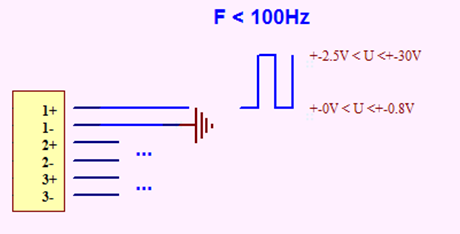
Binary input
Input controlled:
- by a dry contact: pinching at the input ground, 10kΩ maximum contact resistance at ground.
- by 0 < VIL< 0.5VDC to deactivate the input and 2.5VDC< VIH< 30VDC to activate the input (10kΩ of serial protection beyond 5VDC).
The terminal marked on the housing corresponds to the ground on the board. Overvoltage protection.
Input connection to a dry contact:
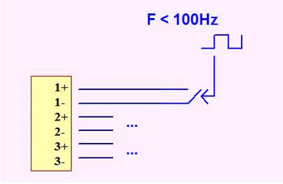
The dry contact must take into account the low polarization current of the input. The use of a silver-or gold-plated contact is recommended to ensure the state is properly detected.
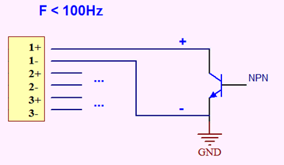
Input connection to a square signal:
Example using a polarized connector:
On/Off output
Electromechanical relay, 10kV insulation between the coil and the contacts.
Breaking capacity of 1A @ 230VRMS under purely resistive load.
Minimum current: 10mA @ 5VDC
Make contact, normally open.
Potential free, dry contact.
This output must be protected from overcurrents by an external device with a rating suited to the output capacity.
Function: status report (fault, deletion...)
Voltage Inputs
Each voltage input is equipped with a stage that allows the voltage to be reduced to a level compatible with the internal sensor input stage.
Each voltage inputs have to be protected by a 1A gG external fuse.
Maximum voltage: 450VRMS
Measurement accuracy: 1%
Current inputs
general
There are 3 current inputs.
In the case of a 4-wire installation, the 3 inputs are used.
In the case of a 3-wire installation, the current in phase 2 is obtained by difference from the other 2. Only measurement points 1 and 3 are used.
It is advice to connect the transformer on the triphaso before mouting transformer on the grid.
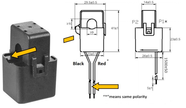
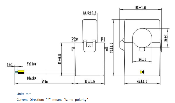
polarity
In order to correctly measure the angle between voltage and current, the polarity must be observed when connecting current transformers. The 2 wires of the secondary circuit must be connected so as to be in the same direction as the primary current. In the event of an error, the phase measurement will be shifted by 180°.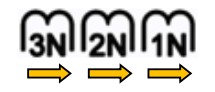 The arrow indicates the direction of polarity to be observed, as per that on the primary of the current transformer.
The best way to connect it is to connect the 'N' ring on the 'N' connector.
0-60A range
Primary current transformation by a current transformer with a 1:3000 ratio @ 50 Hz (supplied)
Measurement accuracy: 3% of full scale (with a Class 2 current transformer)
0-400A range
Primary current transformation by a current transformer with a 1:5000 ratio @ 50Hz (supplied)
Measurement accuracy: 3% of full scale (with a Class 1 current transformer)
0-4000 A range
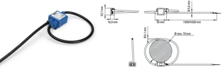
Transformation of the primary current by a Rogowski coil with a ratio of 22.5 mV/kA @ 50 Hz (not supplied)
Measurement accuracy: 3% of full scale (with a Class 0.5 Rogowski coil)
Electrical installation
Each voltage inputs have to be protected by a 1A gG external fuse.
Triphas'o can answer to several type of electrical network:
Mono-phase
On Mono-phase, it is possible to connect 1 to 3 current transformers on the same phase. If there is more than 1 current transformer then it is necessary to link L1, L2 and L3 to have a measurement of voltage, angle and power of all inputs.
On Mono-phase, the Voltage inputs must be connected as following:
| Phase | Triphas'O Terminal Block |
| Phase | L1 |
| Phase | L2 [if more than 1 current transformer] |
| Phase | L3 [if more than 1 current transformer] |
| Neutral | N |
On this installation, it is necessary to set the Triphas'o in single-phase configuration (Star + Delta LEDS on).
Three-phase
On this, there is several possibilities 4-wires and 3-wires.
The order of the phases is determined by looking at when each goes to 0. There is direct order and reverse order.
- Direct order: the voltages appear in the order L1, L2 and L3.
- Inverse order: the voltages appear in the order L1, L3 and L2.
In the following, the order of phases is considered as direct.
The typical representation diagram of voltage and current vectors is:
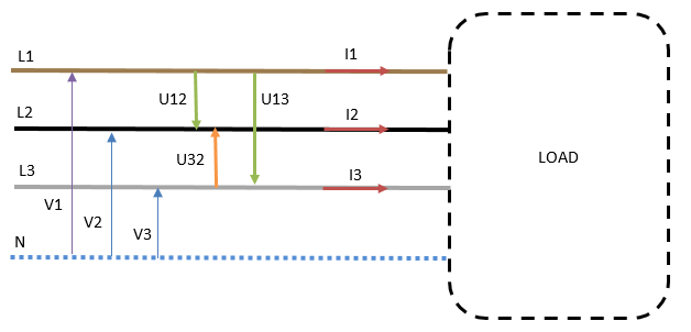
The following description will be based on this previous schema.
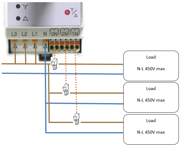
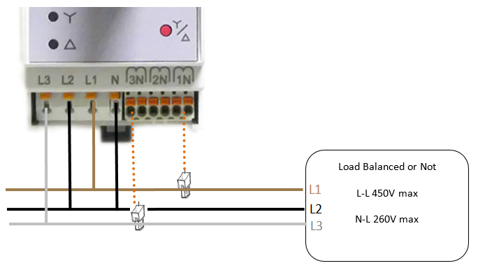
4-wires (3P +N)
The 4 wires can be installed on this typical use case:
On Three-phase - 4 wires, the Voltage inputs must be connected as following:
| Electricity grid |
Triphas'O Terminal Block |
| Phase L1 | L1 |
| Phase L2 | L2 |
| Phase L3 | L3 |
| Neutral | N |
If "error" red led is ON, then inversed L2, L3 on the Triphas'O terminal block, and verify than the 3 current transformaters are on the right phases.
On this installation, it is necessary to set the Triphas'o in 4-wire configuration (Star).
On this, the return values by Triphas'o of voltage, intensity and angle is :
| EndPoint | Voltage | Current | Angle |
| 0 | V1 | I1 | (I1,V1) |
| 1 | V2 | I2 | (I2,V2) |
| 2 | V3 | I3 | (I3,V3) |
Measurement in balanced 3-phase 4-wire (3 phases + neutral) system:
The currents flowing in the three phases are equal in RMS values I1 = I2 = I3 and have the same phase shift ϕ with respect to the respective voltages of the 3 phases.
So with V1 as the single-phase voltage measured between phase L1 and neutral, the power P1 supplied by phase L1 will be obtained by connecting only one wattmeter on the phase L1. The value will be: P1 = V1 x I1 x cos ϕ and total power P = 3 x P1.
Measurement in unbalanced 3-phase 4-wire (3 phases + neutral) system:
In this case, it is necessary to use 3 wattmeters and the measurement of each power need to be added.
P = P1 + P2 + P3
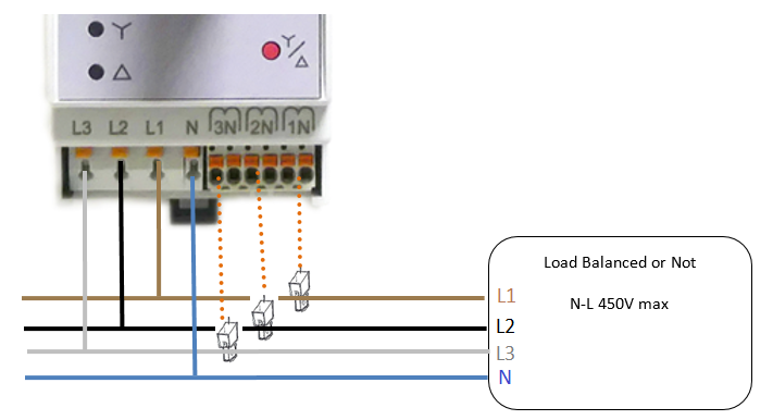
3-wires (3P)
The 3 wires can be installed on this typical use case:
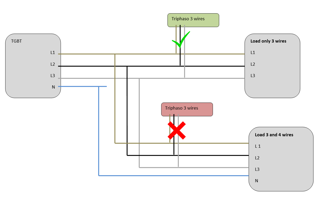
It is not possible to connect Triphaso on 3 wires mode, if there is load behind connected on 3 wires + neutral or on mono-phase. If the Load is not balanced then there is possibility to have current on the neutral which will be not measured by the Triphaso.
On Three-phase - 3 wires, the Voltage inputs must be connected as following:
| Electricity grid |
Triphas'O Terminal Block |
| Phase L1 | L1 |
| Phase L2 | N - L2 [Optional] |
| Phase L3 | L3 |
If "error" red led is ON, then inversed L2, L3 on the Triphas'O terminal block, and verify than the 2 current transformaters are on the right phases.
On this installation, it is necessary to set the Triphas'o in 3-wire configuration (Delta). The measurement is done with the method of 2 wattmeters. In this method, only 2 input currents are necessary and has to be installed on Phase 1 and Phase 3. Due to this method, if load is not balanced, only the active power measurement is valid.
On this, the return values by Triphas'o of voltage, intensity and angle is :
| EndPoint | Voltage | Current | Angle |
| 0 | U12 | I1 | (I1,U12) |
| 1 | U13 | I2 | (I2,U13) |
| 2 | U32 | I3 | (I3,U32) |
The fresnel graph is the following:
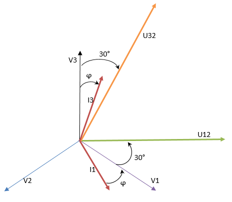
So, it is possible to have the angle (In,Vn) by calculation:
| (I1,V1) | = (I1,U12) - 30° |
| (I2,V2) | = (I2,U13) - 90° |
| (I3,V3) | = (I3,U32) + 30° |
On this method, it is necessary to add the power or energy of the Phase 1 and Phase 3 to have the total power or energy. It is possible to have a negative power and energy on Phase 1 if the (I1,V1) is > 60°; or on Phase 3 if (I3,V3) < -60°. So to have the total powers and energies, it is necessary to add the Positive and Negative powers and energies.
Ptotalpositive = P1positive + P3positive
Ptotalnegative = P1negative + P3negative
Ptotal = |Ptotalpositive| - |Ptotalnegative|
Radio propagation
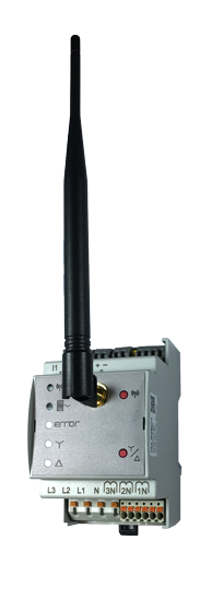
A female SMA connector is mounted on the front panel to allow the connection of an antenna or an
extension for a remote antenna.
Human Machine Interface
The Human Machine Interface has 5 leds and 2 buttons:
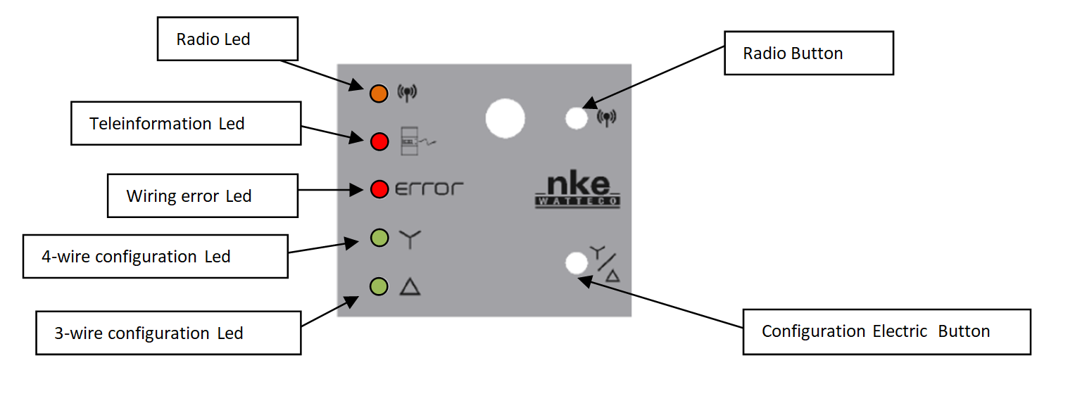
Radio Network
To start up the device, the radio button has to be pushed on the sensor for one second. After one second, the radio Led blinks slowly until the association is done. Since release v3.5.2.5530, after 6 hours in assosation searching the led blinks all 1 minute.

To switch off the device, repeat the same operation by pressing the radio button for 5 seconds. After those 5 seconds, the radio Led blinks 5 times slowly.
- A reassociation procedure can be requested if no downlink frame is received by the sensor during a given periodicity (4 days by default) or if a given number (100 by default) is reached or in case of failure (no acknowledgement received) by sending an applicative frame to the sensor or via the sensor’s IHM.
The sensor keeps the AppEUi and DevAddr configured, Confirmed/Unconfirmed configuration and all applicative configurations. However, LoRaWAN configurations (channel, data rate …) are lost.
Feature is available by pushing 3 quick times on the radio button.
- A factory reset is available on Watteco’s sensors. It deletes all the applicative settings saved in the flash memory (i.e. configured batches and reports will be deleted).
The sensor keeps the AppEUi and DevAddr configured. However, LoRaWAN configurations (channel, data rate…) and applicative configurations are lost.
Feature is available by pushing two quick times and a long time on the radio button.
Electrical Configuration
These keys and leds are used to configure the sensor in the appropriate type of installation.
- “4-wire” type installation, or
- “3-wire” type installation, or
- single-phase installation.
With each press on Configuration Electric Button, the sensor switches between the three modes. To tell the installer which mode the sensor is in, the latter will switch on:
- the "4-wire configuration" LED only (4-wire mode), or
- the "3-wire configuration" LED only (3-wire mode), or
- these 2 LEDs simultaneously (single-phase mode)
Applicative layer
Codecs are available to decode frames: Downloads
Encoder are available on Online Codec
Triphas'o incorporates the following clusters:
| cluster | cluster name | managed attributes |
|---|---|---|
| 0x0000 | Basic | All |
| 0x0050 | Configuration | All |
| 0x0006 | ON/OFF | All |
| 0x000F | Binary Input | All |
| 0x8004 | LoRaWAN | All |
| 0x800A | Energy and power metering | All |
| 0x800B | Voltage an current metering | All |
| 0x8010 [available from v3.5.2.6041] | Multi Energy and power metering | All |
| 0x800D [available from v3.5.2.6041] | Multi Voltage an current metering | All |
Triphas'o measures each second positive, negative active and reactive power, Vrms, Irms et Phase angle between voltage and current.
It is possible to modify the periodicity of integration of powers and so the resulted power is the mean on this periodicity.
The unit of energies are configurable in Wh/VARh or kWh/kVARh with a specific configuration frame, for each phase. (Only available starting from Build v3.5.2.5781)
Triphas'o implements “Energy and power metering” and "Voltage an current metering" clusters. The corresponding between the phase and the EndPoint are shown below:
| Connector | End Point | Cluster | Fctrl |
|---|---|---|---|
| Phase A | 0 | Energy and power metering / Voltage and current metering | 0x11 |
| Phase B | 1 | Energy and power metering / Voltage and current metering | 0x31 |
| Phase C | 2 | Energy and power metering / Voltage and current metering | 0x51 |
| Phase A+B+C | 3 | Energy and power metering | 0x71 |
"Multi Energy and power metering” and "Multi Voltage an current metering" clusters integrate all phases in the same frame.
Default configuration
A default configuration is set:
- The device reports each hour the voltage, current and angle.
- The periodicity of integration of powers is one hour for each phase and for the summation of phases.
- The device reports each hour the energy meter and mean power for each phase and for the summation of phases. For Rogowski version the energies are by default in kWh and kVARh.
Frame examples
All frames have to be sent on port 125
Standard report
Report
Report on voltage, current and phase measurements11 0a 80 0b 0000 41 06 090d 0066 0167
11 : Phase A
090d : Voltage in 1/10th V 0x090d = 2317 ≡ 231.7V
0066 : Current in 1/10th A 0x0066 =102 ≡ 10.2A
0167 : Angle (degree) between voltage and current 0x0167 =359° = -1°
Report on energy and power measurements
71 0a 80 0a 0000 41 20 0000103c 00000001 00000000 00000016 00000937 00000000 00000000 0000000c
71 : Phase A + Phase B + Phase C
0000103c : Positive active energy 4156 Wh or kWh
00000001 : Negative active energy 1 Wh or kWh
00000000 : Positive reactive energy 0 VARh or kVARh
00000016 : Negative reactive energy 22 VARh or kVARh
00000937 : Positive active power 2359 W
00000000 : Negative active power 0 W
00000000 : Positive reactive power 0 VAR
0000000c : Negative reactive power 12 VAR
Report on binaryinput state
11 0a 00 0f 00 55 10 00
00 : active input
Configuration
Configure a voltage, current and angle report on phase A1106800B000000410000803C06000000000000
11: Phase A
0000 : Min Report = 0 (hence no min report)
803C : Max Report = 80 00 || 00 3C with 00 3C = 60 minutes = 1 hr
0000 : Variation on voltage (1/10th V) to trigger a report (0 = no report on variation)
0000 : Variation on current (1/10th V) to trigger a report
0000 : Variation on angle to trigger a report
=> expected response: 1107800b00000000
Configure an energy and power report on phase B
3106800A000000410000803C20 00000000 00000000 00000000 00000000 00000000 00000000 00000000 00000000
31: Phase B
0000 : Min Report = 0 (hence no min report)
803C : Max Report = 80 00 || 00 3C with 00 3C = 60 minutes = 1 hr
00000000 : Variation on positive active energy (Wh or kWh) to trigger a report (0 = no report on
variation)
00000000 : Variation on negative active energy (Wh or kWh) to trigger a report
00000000 : positive reactive energy (VARh or kVARh)
00000000 : negative reactive energy (VARh or kVARh)
00000000 : Variation on positive active power (W) to trigger a report
00000000 : negative active power (W)
00000000 : positive reactive power (VAR)
00000000 : negative reactive power (VAR)
=> expected response: 1107800A00000000
Configure a one hour periodicity for the mean powers calculation on Phase C
5105 800A 0001 23 00000E10
51: Phase C
0E10 : Time basis for mean power calculation 0E10 = 3600 seconds = 1 hour
Configure the energies unit in kWh/kVARh on Phase A+B+C
71 05 800a 0002 20 01
71: Phase A+B+C
01: energies unit in kWh and kVARh. [00 to be in Wh and VARh]
Configure a binaryinput report
11 06 00 0F 00 00 55 10 00 00 80 0A 01
00 00 : immediate transmission in case of state variation
80 0A : maximum report (= 10 minutes). This allows a report to be issued on start-up to know
the state of the input during installation. With FF FF: no report during the period.
01 : report on change of state
=> expected response: 1107800F00000055
Known Issues
- Recorded Index during power cycle:
- version : V3.5.2.5919
- Issue: the recording index is only done on the variable which have the actual unit of energy. After a power cycle, if a change of unit is done then the new index will be not the right.
- Mean Power Delay:
- Version: V3.5.2.5843
- Issue: Bad power, energies after a mean power calculation modification
- Workaround: Need to reboot the device physically by pushing button or send this following frame on fport 125: 1150005000
- Reactive powers and energies:
- Version: V3.5.2.5465 and under
- Issue: The Reactive values are not correct due to a bad coefficient
- Workaround: All reactive powers and energies must be multiplied by 3,599.
- Delta mode - sum of energies and powers:
- Version: V3.5.2.5843 and under
- Issue: Values on EndPoint 3 of "Energy and power metering / Voltage an current metering" cluster are not correct. The calculation adds Phase 1 + Phase 2 + Phase 3, but in the delta mode only Phase 1 and Phase 2 has to be added.
- Workaround: Use only EndPoint 0 and EndPoint 2 of "Energy and power metering / Voltage an current metering" cluster and add together to have the right value.
- Synchronise sending of Phase1 and Phase3
- set a mean power delay on phase 1 and phase 3 at the same long value. exemple: 60 min
- Configure a reporting on each phase 1 and 3 with a min delay to 1sec to scan the power each second and a delta to 1 to produce a report as soon as the power change (at the end of mean mean power delay), example:
- set a mean power delay on phase 1 and phase 3 at the same long value. exemple: 60 min
- Synchronise sending of Phase1 and Phase3
