Press'O sensor
Declaration of conformity
Download the declaration of conformity
Presentation
The Press'O sensor is a LoRaWAN class A sensor that manages two different power supplies: one is external and may range from 9V to 24V, the other one is internal on the battery.
The Press'O sensor incorporates 2 analog inputs. It also includes an internal antenna.
The Press’O sensor can be used with First Sensor gauge type CTE/CTU/CTW 8000. The probe should be dimensioned so that the maximum height of the fluid does not exceed the maximum pressure allowed by the probe.
The Press'O sensor is also compatible with Huba Control's level sensing pressure transmitter Type 712.
Family code:
The family code of Press'O devices is: 50-70-017-xxx
Known issue:
external power reading
On 50-70-017-004, the external power is not read correctly. It is necessary to use the following formula:
External Voltage = Read Voltage * 1.2075
Electronic specification
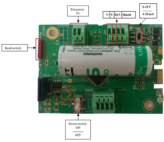
To select the 4-20mA mode or the 0-10V mode, the switch must be put in the right position.
The load resistance on 0-10V input is 10KOhm.
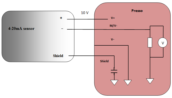
4-20mA mode
• In the 4-20mA mode, the V+ (power supply of the external sensor) is powered during 120ms at 10V.
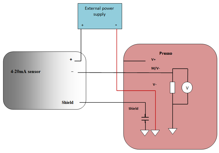
• To add an external power supply, make the following connections:
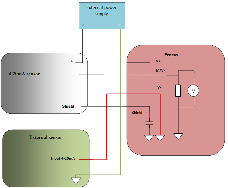
• A series connection can be made with the Press'O and another sensor with a 4-20mA input.
0-10V mode
In the 0-10V mode, the V+ (power supply of the external sensor) is powered during 120ms at 14V with a maximum current of 50mA.
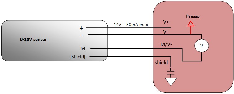
On the Press'O: V+ is the output power supply, V- is the ground, M/V- is the measurement input.
On the sensor: + is the input power supply , - is the ground, and M is the measurement output.
Installation and operation
Installation
The housing is intended to be installed inside or outside a building but it must be protected from vertical water spray and direct sunlight.
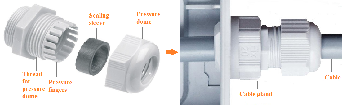
The product is delivered disassembled. This enables the connection to the screw terminals.
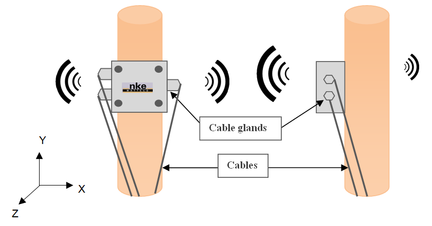
Before connecting your cable strands to the product’s screw terminals, you must insert the cable gland's nut and the seal.
Then connect the wires to the Inputs that will be used:
For the connectors,we recommend using several 20-26 AWG single wires. As the connectors pinch the wires plugged inside approximately 4mm from the wire end, strip the wires over a length of approximately 5 to 6mm before plugging them into the connectors.
Once the assembly is complete, the casing can be closed.
The housing is compatible with the following DIN rail adapter:
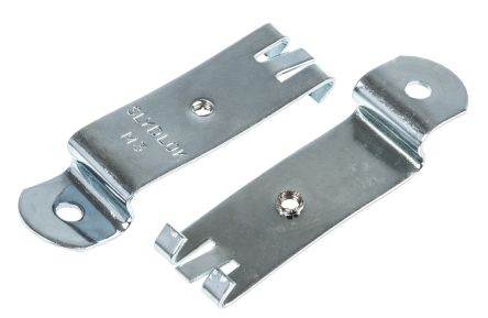
For more information about the casing, please visit: www.spelsberg.com
Radio propagation
In order for the sensor to operate correctly, the number of obstacles should be limited in order to avoid excessive radio wave attenuation. It is also important to place the sensor as high as possible. The Press'O sensor has 3 cable glands, which should be positioned horizontally.
Autonomy
The information in the table below represents how long the battery can last. It is based on the default configuration at ambient temperature (+25°C) within the optimal operating range of the sensor via a LoRaWAN network (one uplink frame), when the spreading factor used is SF12.
The disposable battery has a 3.6Ah capacity, of which 85% is used.
| Transmission periodicity | Battery life |
|---|---|
| 2 frames/ 24 hours | 10 years |
Human Machine Interface
The Press’O sensor has a buzzer that allows it to “communicate” with the user.
Once the device is installed, switch the power ON to start up the device. The buzzer rings until an association is made.
When the sensor is trying to associate with a network, it emits the following sound:
Once the association is completed, the buzzer makes the following sound:
A reed switch (or magnetic switch) is available. A magnet can be used to activate it and perform specific actions on the sensor (switch off, switch on, reassociation…).
- Configuration: "void" frames are sent every minute for 10 minutes.
Standard reports are disabled in this mode.
| Way to trigger it | One passage of the magnet near the reed switch or specific ZCL command |
| Way to stop it | Another passage of the magnet or specific ZCL command |
| Effects on the sensor | |
| Duration | The configuration mode lasts 10 minutes |
- A reassociation procedure can be requested if no downlink frame is received by the sensor during a given periodicity (4 days by default) or if a given number (100 by default) is reached or in case of failure (no acknowledgement received) by sending an applicative frame to the sensor or via the sensor’s IHM.
The sensor keeps the AppEUi and DevAddr configured, Confirmed/Unconfirmed configuration and all applicative configurations. However, LoRaWAN configurations (channel, data rate…) are lost
| Way to trigger it | Three passages of the magnet near the reed switch or ZCL command from LoRaWAN cluster. |
| Effects on the sensor | |
- A factory reset is available on Watteco’s sensors. It deletes all the applicative settings saved in the flash memory (i.e. configured batches and reports will be deleted).
The sensor keeps the AppEUi and DevAddr configured. However, LoRaWAN configurations (channel, data rate…) and applicative configurations are lost.
| Way to trigger it | Two quick passages and a very long passage (until the sensor rings for the reset) of the magnet near the reed switch |
| Effects on the sensor | |
Applicative layer
Codecs are available to decode frames: Downloads
The Press'O device implements “Analog Input” cluster associated to its Inputs. The link between the connectors and the EndPoint is given below:
| Connector | End Point | Cluster | Unit |
|---|---|---|---|
| V+ | M/V- | 0 | Analog Input [4-20mA] | mA |
| V+ | V- |M/V- | 1 | Analog Input [0-10V] | mV |
Press'O integrates the following clusters:
| Cluster | Cluster name | Managed attributes |
|---|---|---|
| 0x0000 | Basic | All |
| 0x0050 | Configuration | All Threshold is available with 3 slots |
| 0x8004 | LoRaWAN | All |
| 0x000C | Analog Input | All Threshold is available with 6 slots |
| 0x000F | Binary Input | All Threshold is available with 4 slots |
Default configuration
A default configuration is set:
- The device reports the 4-20 mA value every 24 hours (EndPoint 0 / Cluster Analog Input / Attribute PresentValue) and the 0-10V value (EndPoint 1 / Cluster Analog Input / Attribute PresentValue).
Every change made to the default configuration must comply with the legal duty cycle (for example, the most restrictive in the EU is 0.1%, which corresponds to approximately 1 frame per hour with SF12)
Measurement periodicity
The measurement periodicity depends on the minimum recording interval.
If the value of the minimum is 0, then the periodicity is 1 second.
If the value of the minimum is different than 0, then this value is the same as the periodicity.
Frame examples
All frames have to be sent on port 125
Standard report
Report
Report of the analog value of connector 4-20mA → Applicative payload is: 11 0a 00 0c 00 55 39 41 50 00 00 11: Fctrl (Endpoint=0) 41 50 00 00: present value (single precision value =>13.0mA)
Report of the analog value of connector 0-10V → Applicative payload is: 31 0a 00 0c 00 55 39 46 14 d0 00 31: Fctrl (Endpoint=1) 46 14 d0 00: present value (single precision value =>9524.0mV)
Configuration
Configure a standard report on the 4-20mA input Report immediately the measurement of the 4-20mA input on a 1mA variation. The measurement has to be reported at least every hour, and the measurement has to be made every 10 minutes. →The 4-20mA is the EndPoint 0, Cluster “Analog Input” is 0x000c, Attribute “PresentValue” is 0x0055. The maximum field has to be 0x0e10 to have a report every one hour and the minimum field has to be 0x800a to have a measurement every 10 minutes. The delta has to be configured to 0x3f800000 for a report every 1mA variation. Applicative payload is: 11 06 00 0c 00 00 55 39 80 0a 0e 10 3f 80 00 00 11: Fctrl (Endpoint=0) 80 0a: minimum reporting interval (10 minutes) 0e 10: maximum reporting interval (1 hour) 3f 80 00 00: reportable change (1mA in single precision) →Response: 11 07 00 0c 00 00 00 55 To disable the previous configuration, change the value of the minimum and maximum sending intervals and the delta to 0: 11 06 00 0c 00 00 55 39 00 00 00 00 00 00 00 00
Configure a standard report on the 0-10V input Report immediately the measurement of the 0-10V input on a 100mV variation. The measurement has to be reported at least every hour, and the measurement has to be made every 10 minutes. →The 0-10V is the EndPoint 1, Cluster “Analog Input” is 0x000c, Attribute “PresentValue” is 0x0055. The maximum field has to be 0x803C to have a report every one hour and the minimum field has to be 0x800a to have a measurement every 10 minutes. The delta has to be configured to 0x42c80000 for a report every 100mV variation. Applicative payload is: 31 06 00 0c 00 00 55 39 80 0a 0e 10 42 c8 00 00 31: Fctrl (Endpoint=0) 80 0a: minimum reporting interval (10 minutes) 80 3c: maximum reporting interval (1 hour) 42 c8 00 00: reportable change (100mV in single precision) →Response:31 07 00 0c 00 00 00 55 To disable the previous configuration, change the value of the minimum and maximum sending intervals and the delta to 0: 31 06 00 0c 00 00 55 39 00 00 00 00 00 00 00 00
Batch report
It is recommended to assign a value of 1mV for the resolution in the 0-10V mode, and a value of 0.01mA in the 4-20mA mode.
• Configure a batch report on analog input and voltage battery:
Timestamp and record the Voltage of a 0-10V sensor with a resolution of 1mV, a value has to be saved at least every 35 minutes or on a 5mV increase. Timestamp and record the battery voltage with a resolution of 0.5V, a value has to be saved at least every 24 hours. All data have to be concatenated and sent every 24 hours at the most.
→The EndPoint of 0-10V is 1, cluster "analog input" is 0x000C, and the attribute "PresentValue" is 0x0055
The battery voltage: Cluster « Configuration » is 0x0050, and attribute « Node power descriptor » is 0x0006.
For analog input, the delta is 0x40a00000(5mV in single precision), and resolution 0x3f800000 (1mV in single precision).
For the disposable battery power voltage, the delta has to be set to 500=0x01F4 (0.5V), the resolution to 500=0x01F4 (0.5V),
There are two different measurements to be recorded in the batch, so the tag size has to be 1. Label 0 can be used for analog input and label 1 for the level of disposable battery.
Two frames must be sent to configure this batch.
| Label number | Tag label | Tag size |
|---|---|---|
| 1 or 2 | 0/1 | 1 |
| 3 or 4 | 00/01/11/10 | 2 |
| 5 or 6 or 7 or 8 | 000/001/010/011/100/101/110/111 | 3 |
| ... | ... | ... |
Applicative payload of the present value of analog input 2+/2- 31 06 00 0c 1d 00 55 00 00 00 80 23 40 a0 00 00 3f 80 00 00 01 31: Fctrl (Endpoint=1) 1d: 0b00011101 => 0001110: size of configuration string after attribute ID (14 bytes) 00 00: minimum recording interval (0 seconds) 80 23: maximum recording interval (35 minutes) 40 a0 00 00: required delta value (size: 4 bytes for attribute PresentValue => attribute type = 39, 5mV in single precision) 3f 80 00 00: required resolution (size: 4 bytes for attribute PresentValue => attribute type = 39, 1mV in single precision) 01: tag value (ob00000001 => 00000: tag label, 001: tag size) →Response: 31 07 00 0c 00 01 00 55
Applicative payload of the battery voltage 11 06 00 50 15 00 06 04 80 0a 85 a0 01 F4 01 F4 09 11: Fctrl (Endpoint=0) 15: 0b00010101 => 0001010: size of configuration string after attribute ID (10 bytes) 04: index of required field (Disposable battery) 80 0a: minimum recording interval (10 minutes) 85 a0: maximum recording interval (24 hours) 01 F4: required delta value (size: 2 bytes for attribute Node power descriptor => attribute type = 41, 0.5V) 01 F4: required resolution (0.5V) 09: tag value (ob00001001=> 00001: tag label, 001: tag size) →Response: 11 07 00 50 00 01 06
To decode the batch reception, use br_uncompress. Type for analog input is ST_FL (12) and U16 (6) for the disposable battery power, so the following command must be used:
echo "26150020e06001d71e0000a0650f" | ./br_uncompress -a 1 0,1,12 1,500,6
Result
DECOMPRESSION SERIES
cnt: 5 # Batch counter (from 0 to 7)
263 # Timestamp in seconds of sending of the frame
# Format of data is: Timestamp of Measurement | Label | Value
263 0 0.000000 # Timestamp: 841 s Label 0: Analog Input Value: 0 V
263 1 3000 # Timestamp: 811 s Label 1: Disposable battery Value: 3.0 V
